Expansion Board 3
Store: Buy Here
Datasheet
The datasheet of the Expansion Board is available as a PDF File
Certifications
The Expansionboard 3 is certified for:
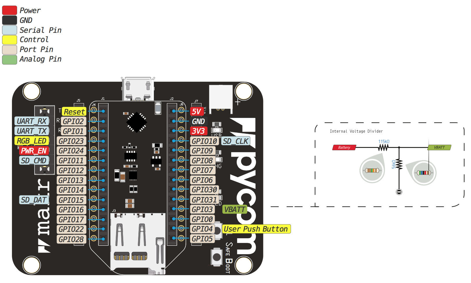
Pinout
The pinout of the Expansion Board is available as a PDF File
The expansion board contains 7 jumpers labeled:
- TX: TX UART (GPIO1) communication of the development board to the Expansionboard
- RTS: Can be used for UART flow control. Connected to GPIO7.
- RX: RX UART (GPIO2) communication of the development board to the Expansionboard
- CTS: Can be used for UART flow control. Connected to GPIO6.
- BAT: Connect the resistor divider on the Expansionboard to the Voltage monitoring ADC Pin (GPIO3)
- LED: Connect the LED on the Expansionboard to GPIO16
- CHG: Removing the jumper will decrease battery charging current from 450mA to 100mA
Note: The internal voltage divider is 1M / 1M, instead of the mentioned values in the pinout. Take care of this when reading the battery voltage.
Be gentle when plugging and unplugging from the USB connector. Whilst the USB connector is soldered and is relatively strong, if it breaks off it can be very difficult to fix.
Notes
Battery Charger
Make sure you check the polarity of the battery before plugging it in! Connect the positive side to the side marked with a
+.
The Expansion Board features a single cell Li-Ion/Li-Po charger with a JST PHR‑2 connector. When the board is being powered via the micro USB connector, the Expansion Board will charge the battery (if connected). When the CHG jumper is present, the battery will be charged at 450mA. If this value is too high for your application, removing the jumper lowers the charge current to 100mA.
To use the battery, pull
P8/G15high (connect to3v3). If you want to use the SD card as well, use a 10k pull-up.
Differences between v2.0 and v3.0
On version 3.0:
-
The FTDI chip as been replaced with a custom programmed PIC, similar to the
Pysense/Pytrack/Pyscan boards. This allows our firmware update tool to
automatically put the module into bootloader mode.
-
Added a “Safe Boot” button to enter more easily into safe boot. This button connects
P12to3.3vand if pressed and held while the reset button is pressed ona Pycom module, the module will enter safe boot.
Differences between v3.0 and v3.1
On version 3.1:
- The green USB-LED is only lit when the USB communication stack is running
- The USB-Serial converter (PIC) is powered using any power source. Previously, it would only power up when the board was powered through USB.
Troubleshooting
- If PIC stays in bootloader mode, the
dfu-utilupdate should be performed
3D model for case design
- Please see the 3D model (step format)