Pytrack 2.0X
The Pytrack 2.0 X shield allows you track your location using the onboard GPS and accelerometer.
Getting started
- Find the libraries for the Pytrack 2.0 X in the Pycom libraries repository on Github.
- Download the files and extract them into the project folder in Pymakr
- Click the
upload project to devicebutton. This will store all necessary files on the device and allow you to import them in the examplemain.py. - Check the REPL. If you have Pybytes activated, the example will send the location data to Pybytes automatically.
Examples
The Pytrack has several examples:
Features

Datasheet
The datasheet of the Pytrack is available as a PDF File
Pinout
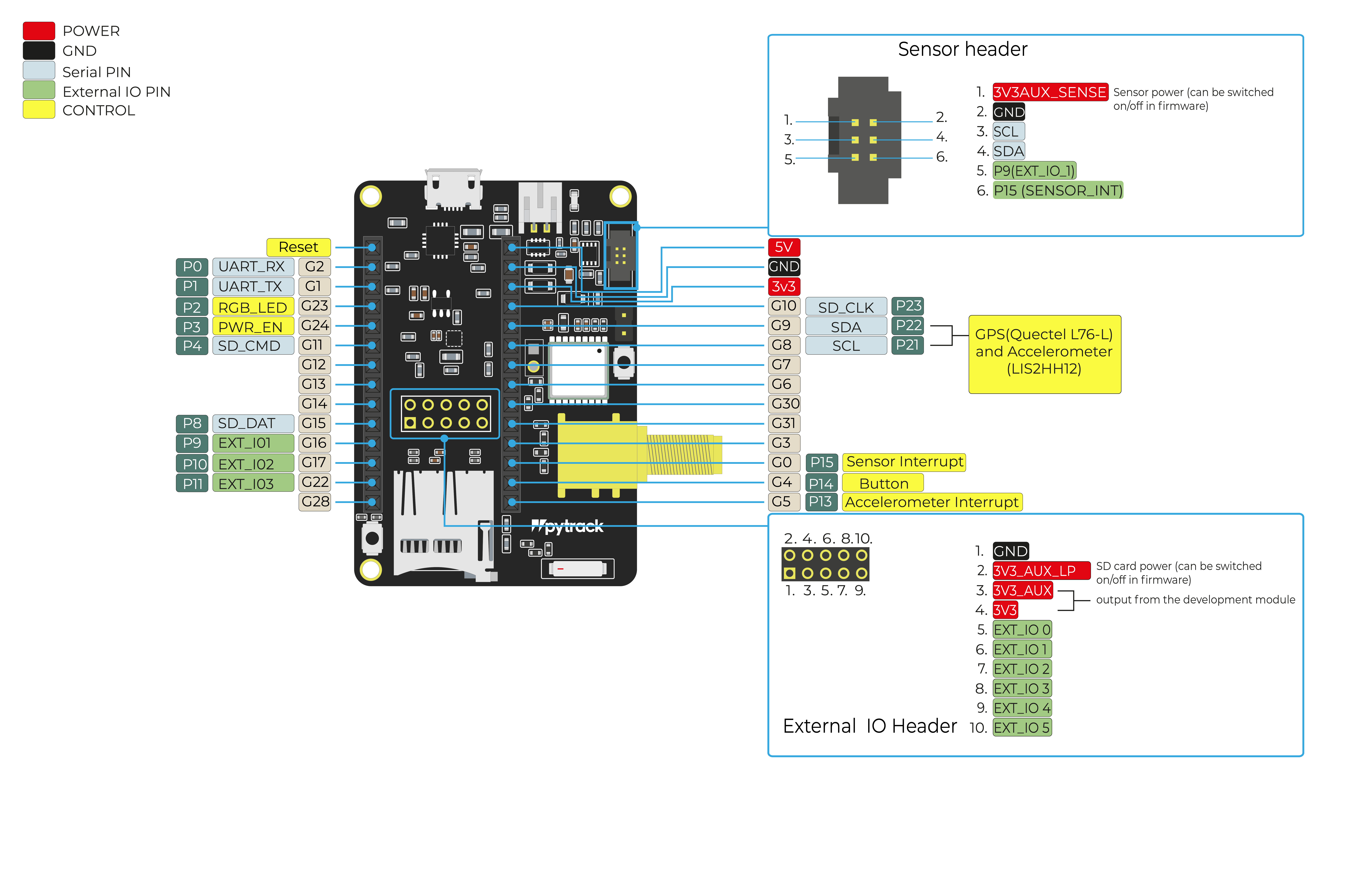
The PyPort connector is for a 6 lead mini ribbon cable. Part: Amphenol 20021511-00006T4LF. The external IO header power pins are labelled as follows
- 3V3AUX - The power provided by the development module
- 3V3AUX_LP - the power provided by the development module for the SD card (This can be switched off)
- 3V3 - The power provided by the Pysense 2, for the USB-Serial converter. This is also used to power the GPS in standby mode.
The Pytrack 2 can be powered through the USB port, the battery connector and the VUSB_AUX header just below the PyPort. Connecting a 5V supply to the header will result in exactly the same behaviour as powering it through the USB connector.
The pinout of the Pytrack is available as a PDF File
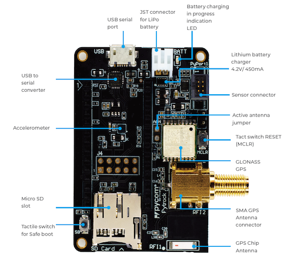
The Pytrack 2.0 X features a SMA connector that allows for the connection of an external active or passive GPS antenna. The SMA connector has an internal switch that switches the connection from the internal to the external antenna automatically upon connection of the external antenna.

Notes
Antenna
The Pytrack 2.0 X board has an internal GPS antenna built in. You can find it on the front side near the bottom, labelled RFI1. When you are not using the external antenna, remove the jumper labeled AON. If you want better reception and faster fix times, you can use the external GPS antenna with the Pytrack 2.0 X. The SMA connector on the side does NOT work with the LoRa or WiFi whip antennas you might already have! You can purchase the appropiate GPS antenna from our webshop here.
Battery Charger
The board features a single cell Li-Ion/Li-Po charger with a JST PHR‑2 connector. When the board is being powered via the micro USB connector, it will charge the battery (if connected).
Make sure you check the polarity of the battery before plugging it in! Connect the positive side to the side marked with a
+.
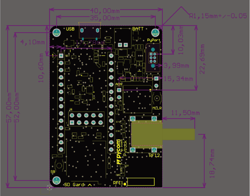
Mechanical Dimensions

3D model for case design
- Please see the 3D model (step format)