WiPy 3.0
Note: Orient the RGB LED / reset button over the USB connector on any expansion board
Store: Buy Here
Getting Started: Click Here
Datasheet
The datasheet of the WiPy3 is available as a PDF File
Certifications
The Wipy 3 is certified for:
Pinout
The pinout of the WiPy3 is available as a PDF File
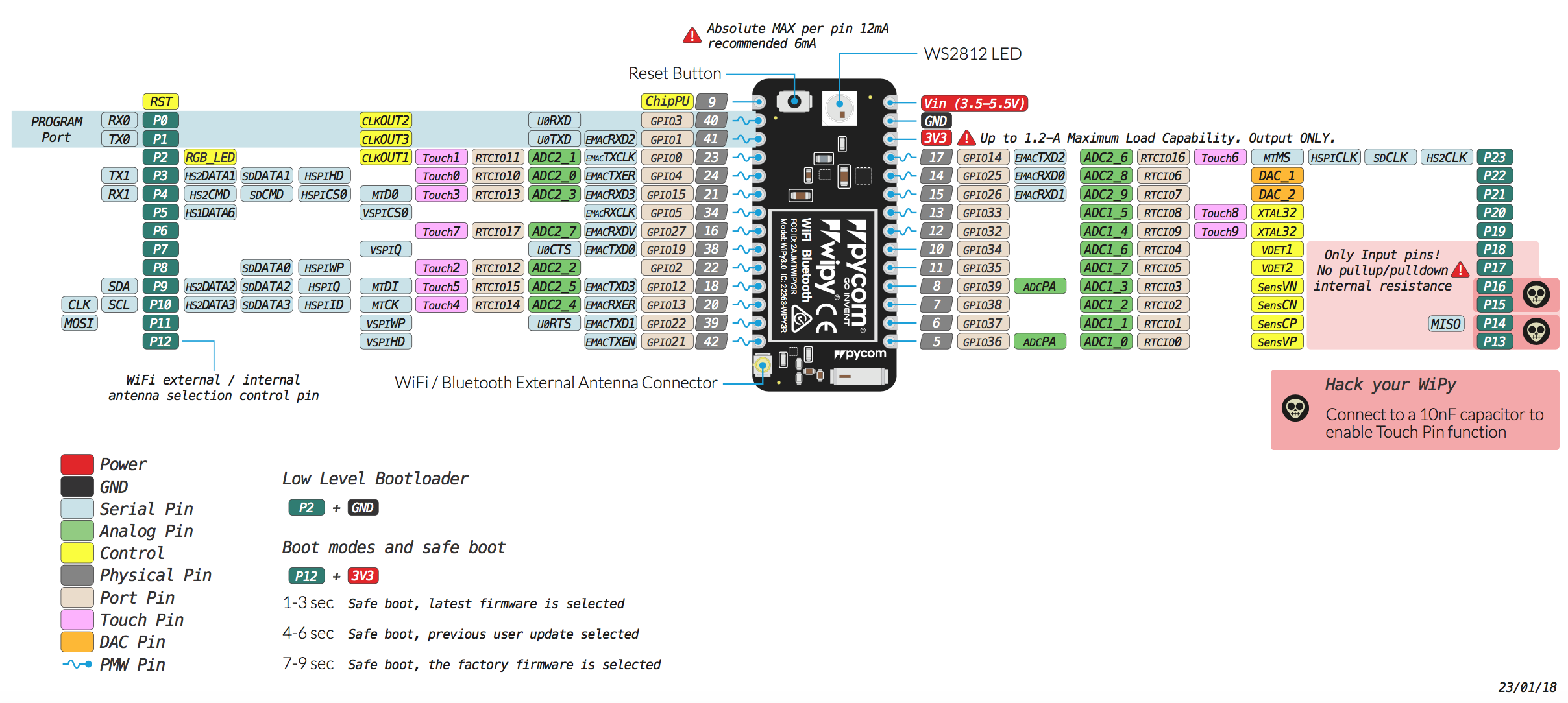
Please note that the PIN assignments for UART1 (TX1/RX1), SPI (CLK, MOSI, MISO) and I2C (SDA, SCL) are defaults and can be changed via software.
Differences from WiPy 2.0
- The Deep Sleep current draw is now fixed - it is only 19.7µA
- The RAM has been upgraded from 512KB to 4MB
- The External FLASH has been upgraded from 4MB to 8MB
- The antenna select pin has moved from GPIO16 to GPIO21 (P12)
Notes
Power
Do not use the 3.3V pin in combination with the Vin pin to supply the device as this will damage the voltage regulator on the board.
Antenna placement
Always attach the appropriate antenna when using a wireless connection. For WiFi / BLE, it is not mandatory to use an external antenna when you did not explicitly specify this in your code.
WiFi
By default, upon booting up the WiPy3 will create a WiFi access point with the SSID wipy-wlan-XXXX, where XXXX is a random 4-digit number, and the password www.pycom.io.
The RF switch that chooses between the on-board and external antenna is connected to P12, for this reason using P12 should be avoided unless WiFi is disabled in your application.
Power
The Vin pin on the WiPy3 can be supplied with a voltage ranging from 3.5v to 5.5v. The 3.3v pin on the other hand is output only, and must not be used to feed power into the WiPy3, otherwise the on-board regulator will be damaged.
Tutorials
Tutorials on the WiPy3 module can be found in the examples section of this documentation. The following tutorials might be of interest for those using the WiPy3: