LoPy
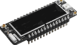
Note: Orient the RGB LED / reset button over the USB connector on any expansion board
Store: Buy Here
Getting Started: Click Here
Datasheet
The datasheet of the LoPy is available as a PDF File
Certifications
The Lopy is certified for:
Pinout
The pinout of the LoPy is available as a PDF File
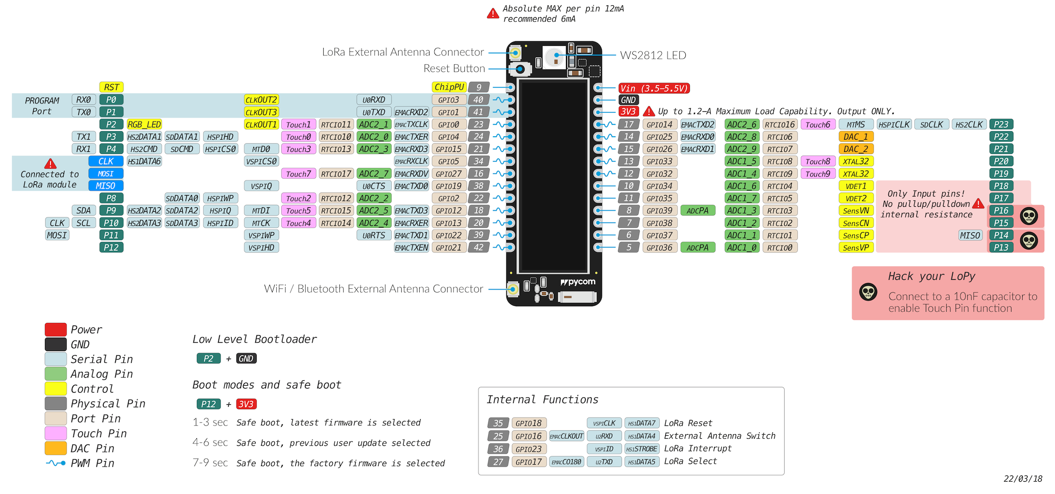
Please note that the PIN assignments for UART1 (TX1/RX1), SPI (CLK, MOSI, MISO) and I2C (SDA, SCL) are defaults and can be changed via software.
Notes
Power
Do not use the 3.3V pin in combination with the Vin pin to supply the device as this will damage the voltage regulator on the board.
Antenna placement
Always attach the appropriate antenna when using a wireless connection (LoRa). For WiFi / BLE, it is not mandatory to use an external antenna when you did not explicitly specify this in your code.
Deep Sleep
Due to a couple of issues with the LoPy design, the module draws more current than it should while in Deep Sleep. The DC-DC switching regulator always stays in high performance mode, which is used to provide the lowest possible output ripple when the module is in use. In this mode, it draws a quiescent current of 10mA. When the regulator is put into ECO mode the quiescent current drops to 10uA. Unfortunately, the pin used to control this mode is out of the RTC domain. This means that it is not usable during Deep Sleep. This results in the regulator remaining in PWM mode, keeping its quiescent current at 10mA. The flash chip also doesn’t enter into power down mode as the CS pin floats during Deep Sleep. This causes the flash chip to consume around 2mA of current. To work around this issue a “deep sleep shield” is available that attaches to the module and allows power to be cut off from the device. The device can then be re-enabled either through a timer or via a pin interrupt. With the Deep Sleep Shield, the current consumption during deep sleep is between 7uA and 10uA depending on the wake sources configured.