LoPy 4
Note: Orient the RGB LED / reset button over the USB connector on any expansion board
Store: Buy Here
Getting Started: Click Here
Datasheet
The datasheet of the LoPy4 is available as a PDF File
Certifications
The Lopy 4 is certified for:
Pinout
The pinout of the LoPy4 is available as a PDF File
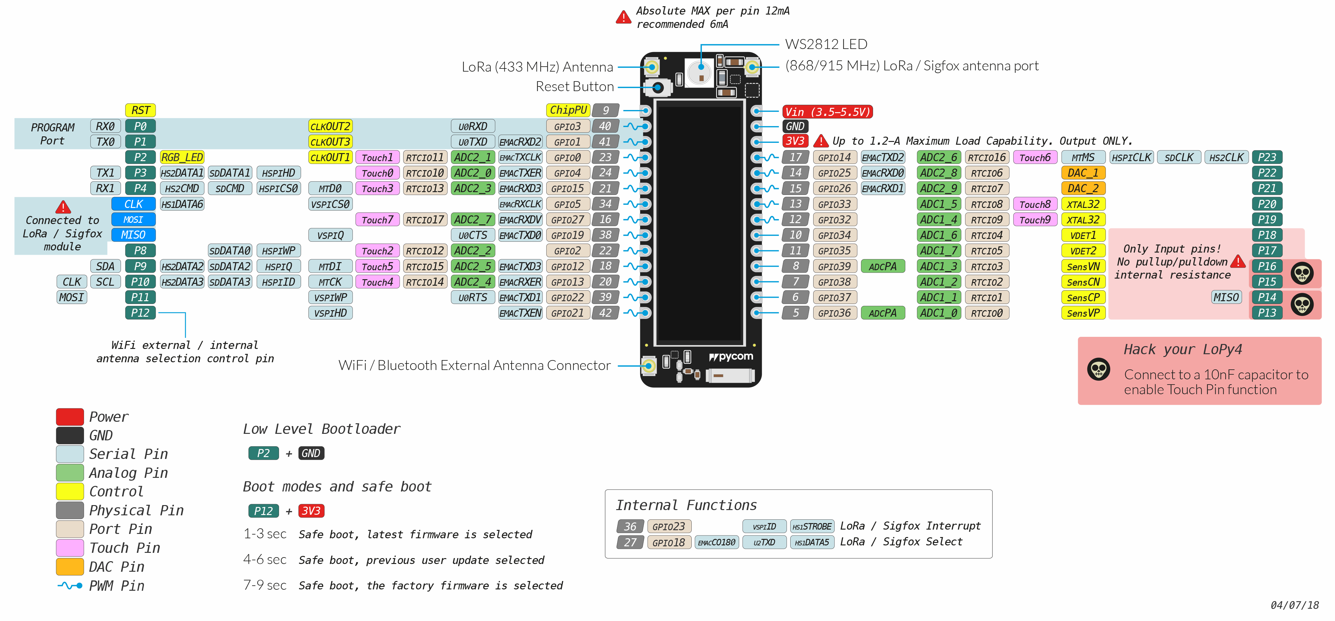
Please note that the PIN assignments for UART1 (TX1/RX1), SPI (CLK, MOSI, MISO) and I2C (SDA, SCL) are defaults and can be changed in Software.
Notes
Power
Do not use the 3.3V pin in combination with the Vin pin to supply the device as this will damage the voltage regulator on the board.
Antenna placement
Always attach the appropriate antenna when using a wireless connection (LoRa / SigFox). For WiFi / BLE, it is not mandatory to use an external antenna when you did not explicitly specify this in your code.
Power
Do not use the 3.3V pin in combination with the Vin pin to supply the device as this will damage the voltage regulator on the board.
Antenna placement
Always attach the appropriate antenna when using a wireless connection (LoRa / LTE). For WiFi / BLE, it is not mandatory to use an external antenna when you did not explicitly specify this in your code.